Speed Sensor Tester
Jaltest SST is a small portable equipment designed to check the correct operation of active and passive speed sensors. It has two operating modes that comprise tests of both the sensor and the ECU to which it is connected.
Through a lighting panel of LED devices, the user can easily detect potential errors without carrying out difficult and complex tests.
This product enables the user to significantly reduce the time spent on checks and fault detection since it allows the detection of the focus of the issue.
GENERAL RULES FOR USE
1 Read the instructions carefully before using the device for the first time.
2 Prevent non-qualified personnel from using the equipment.
3 Prevent the equipment from getting wet with water or other liquids.
4 Store the equipment and its components inside their box and in a dry place,away from heating sources and out of reach of sunlight.
5 Prevent the equipment from being knocked and falling out.
6 Turn off the equipment after being used to save battery life.
EQUIPMENT COMPOSITION
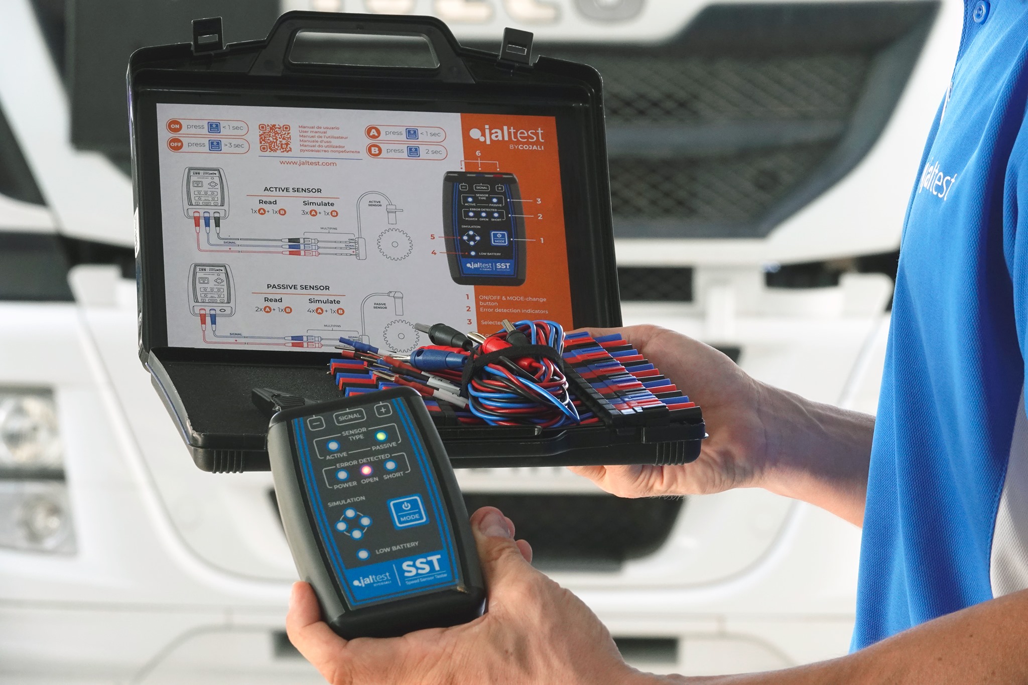
Jaltest SST is made up of an electronic device with an operating interface with a button and LEDs, as well as a complete kit of cables and multipins that allow connection in the sensor and ECU connector pins. It has a 9 V alkaline battery type 6LR61. 1. On/Off & mode change button This mode allows the user to interact with the device. There are 3 press types:
Short press (less than 1 s): It changes mode when no mode is selected. If a mode is selected, it carries out a specific action of the mode.
Long press (between 1 s and 3 s): It selects the desired mode. If a mode is already selected, it returns to start mode.
2. Error detection
A red LED lights up if an open circuit, short circuit, or power supply problem is detected.
3. Sensor type
A green LED indicates whether an active or passive sensor is being read or simulated.
4. Low Battery
A red LED lights up if the battery is too low.
5. Simulation LEDs and signal status
In simulation/read mode, 4 green LEDs flash sequentially clockwise, indicating that the signal is being simulated/read.
6. Connections
3 banana female connectors. The connection positions; power supply (red), signal
(blue), and ground (black) are indicated in the upper part of the control panel.
Procedures
· ACTIVE speed sensor:
In this mode, the speed sensor is disconnected from the ECU and connected to the Jaltest SST device to be able to check it in isolation. By turning the component whose sensor the user wants to check, they can determine if the sensor generates a correct signal.
1. Disconnect the speed sensor from the vehicle and connect it to the Jaltest SST device through multipins according to the IMAGE 1 of the connection diagram section.
2. Turn on the device and go into Active Sensor Read mode interacting with the selection button of the mode (1) according to the presses described in the function table. The Active Sensor LED must be on, as well as the LED of the errors that may appear.
3. Turn the component whose sensor you want to check.
4. Signal check: When the component is turning at constant speed, the status LEDs of the signal must flash sequentially, clockwise, and consistently.
5. Error check:
a) The status LEDs of the signal flash inconsistently: The sensor does not detect a consistent turn signal.
b) The short circuit error LED lights up: Short circuit to power supply has occurred during the execution of the test.
c) The power supply error LED lights up: Incorrect mode has been selected (simulation).
Note: It is possible to repeat the test with just a short press of the selection button of the mode. The device performs an error reset and starts the test again.
· PASSIVE speed sensor:
In this mode, the speed sensor is disconnected from the ECU and connected to the Jaltest SST device to be able to check it in isolation. By turning the component whose sensor the user wants to check, they can determine if the sensor generates a correct signal. For example, by manually turning a vehicle wheel with speed sensor.
1. Disconnect the speed sensor from the vehicle and connect it to the Jaltest SST device through multipins according to the IMAGE 2 of the connection diagram section.
2. Turn on the device and go into Passive Sensor Read mode interacting with the selection button of the mode (1) according to the presses described in the function table on page 6. The Passive Sensor LED must be on, as well as the LED of the errors that may appear.
3. Turn the component whose sensor you want to check.
4. Signal check: When the wheel is turning at fixed speed, the status LEDs of the signal must flash sequentially and constantly.
5. Error check:
a) The status LED of the signal flash inconsistently: the sensor does not detect a consistent turn signal.
b) The open circuit error LED lights up: Wiring or sensor is defective.
c) The short circuit error LED lights up: Short circuit to ground (chassis) or power supply has occurred during the execution of the test.
d) The power supply error LED lights up: Incorrect mode has been selected (simulation).
Note: It is possible to repeat the test with just a short press of the selection button of the Mode. The device performs an error reset and starts the test again.
SIMULATION MODE
Important! Jaltest SST cannot operate as a substitute for the vehicle speed sensor so, in some cases, it is normal that the ECU has present errors concerning the disconnected component.
ACTIVE speed sensor:
In this mode, the Jaltest SST device generates a signal that simulates the behaviour of an active sensor. When connecting the Jaltest SST device to the ECU and with the help of a diagnosis device that shows the speed read by the ECU, the user will be able to detect errors in the wiring or in the control unit itself.
1. Disconnect the speed sensor from the vehicle and connect instead the Jaltest SST device through multipin cable kit according to the IMAGE 3 of the connection diagram section (it is possible to connect multipins to the ECU or to an intermediate connector).
2. Turn on the device and go into Active Sensor Simulation mode interacting with the selection button of the mode (1) according to the presses described in the function table on page 6. The imulation and Active sensor LEDs must be on, as well as the LED of the errors that may appear.
Note: In case that the short circuit error appears in the Jaltest SST device, it can be removed once step 3 is being carried out with just a short press of the selection button of the Mode.
3. Turn the ignition key of the vehicle to the ignition key position.
4. Use a diagnosis software to
verify that the ECU is reading the speed simulated by the device (if you do not have a diagnosis device, go to step 5). If the ECU is not reading the speed, perform short presses of the selection button of the mode (1) to reset the present errors and adjust the signal frequency gradually so that it can be read by the ECU:
Note: The speed read depends on the vehicle ECU and can vary significantly depending on it.
5. Error check:
a) The power supply error LED lights up: There is an error in the sensor power supply cable or the ECU does not provide the appropriate voltage for this cable.
b) The short circuit error LED lights up: Short circuit to ground (chassis) or power supply has occurred during the execution of the test.
PASSIVE speed sensor:
In this mode, the Jaltest SST device generates a signal that simulates the behavior of an active sensor. When connecting the Jaltest SST device to the ECU and with the help of a diagnosis device that shows the speed read by the ECU, the user will be able to detect errors in the wiring or in the control unit itself.
1. Disconnect the speed sensor from the vehicle and connect instead the Jaltest SST device through multipin cable kit according to the IMAGE 4 of the connection diagram section (it is possible to connect multipins to the ECU or to an intermediate connector).
2. Turn on the device and go into Passive Sensor Simulation mode interacting with the selection button of the mode (1) according to the presses described in the function table on page 6. The Simulation and Passive sensor LEDs must be on, as well as the LED of the errors that may appear.
Note: In case that the short circuit error appears in the Jaltest SST device, it can be removed once step 3 is being carried out with just a short press of the selection button of the Mode.
3. Turn the ignition key of the vehicle to the ignition key position.
4. Use a diagnosis software to verify that the ECU is reading the speed simulated by the device* (if you do not have a diagnosis device, go to step 5). If the ECU is not reading the speed, perform short presses of the selection button of the mode (1) to reset the present errors and adjust the signal frequency gradually so that it can be ready by the ECU. In ABS sensors, the following speeds are common:
* In case of not being able to connect to the system to perform the speed reading, try to connect with the Jaltest SST device without going into the Passive Sensor Simulation mode. Once in the system, go into the Passive Sensor Simulation mode to be able to read the speed values.
Notes:- The speeds shown in the above table are merely indicative. The speed read depends on the vehicle ECU and can vary significantly depending on it. - If the speed cannot be read with the connections of IMAGE 4 of the connection diagram section, try to invert the «+» and signal connections. If the speed is still not read, use the connections of IMAGE 5 (ground connection). As a last step, invert the «+» and signal connections
5. Error check:
a) The power supply error LED lights up: There is an error in the sensor power supply cable or the ECU does not provide the appropriate voltage for this cable or the ECU connector in which we have connected to is not for a passive speed sensor.
b) The short circuit error LED lights up: Short circuit to ground (chassis) or power supply has occurred during the execution of the test.
Technical data
- Device size: 118 x 79 x 32 mm
- Case size: 350 x 230 x 86 mm
- Device weight: ~ 180 g
- Complete case weight: ~ 1200 g
- As security measure and in order to avoid the total battery discharge, the Jaltest SST device automatically disconnects the power supply of the electronic board when it detects an inactive period longer than 5 minutes.
- Working temperature range: From -10 ºC until 40 ºC.
Other Post
New Ampro SCR Doser Testing Machine
Jaltest Commercial Vehicle Scanner
JALTEST SST
Jaltest Telematics